Layer 2-3
Notes before use
Oplon Global Distributed Gateway ADC layer 2-3 is the layer 2-3 balancing feature that allows you to balance connections by making the DNAT of the source IP address.
You must use Oplon 9.9.0 or higher to use the OplonADC layer 2-3 feature. If you come from releases less than 9.9.0, you must update to a new release with the utility available on the Oplonsite (see manual OPLON_GDG_InstallUpdate) and update the operating system over an Internet connection.
TCP and UDP Layer 2-3 Packet Manager
Oplon ADC layer 2-3 uses the kernel packet routing queuing system that is set through the iptables commands to be processed by Oplon.
Two queues are used for each stream, the first receiving packets from the client through a network interface, the second receives response packets from endpoints through another network interface.
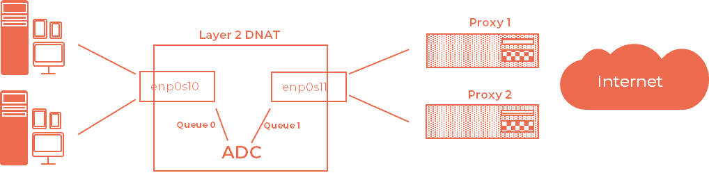
In the following example, two proxies receive traffic from within the layer 2-3 balanced datacenter and return packets to their respective interfaces to the ADC system.

Requests that come from clients to the enp0s10 interface exit the enp0s11 interface with the same IP as the client modified by the ADC. Once processed by proxies, response packets are routed to the ADC, which re-modulates packets to deliver the response to clients that have requested them.
The client and server request ports can be different, they will also be changed by the ADC during the exchange.
To create The Layer 2-3 queues, you must act at 2 levels:
-
Generating IP stack-level input and exit queues
-
Setting up adC queue usage for packet processing
IP Code Creation
TO manage layer 2-3 packets and their routing, Oplon ADC uses the code manager built with iptables.
For each LOGICAL stream Oplon ADC uses 2 queues, the first associated with the communication interface with clients, the second associated with the communication interface to the services. The queues are numbered for use by Oplon ADC.
Oplon ADC can handle countless streams associated with countless queues simultaneously.
For example, the following diagram takes the use of the Layer 2-3 component to balance and load up reliability two proxies. Queue 0 is associated with the network adapter to clients, queue 1 is associated with the network adapter to the proxies.
To run the queues setup run the following commands from root.
For TCP/IP
# iptables -t mangle -A PREROUTING -i enp0s10 -p tcp -s 192.168.43.0/24
-j NFQUEUE --queue-num 0
# iptables -t mangle -A FORWARD -i enp0s17 -p tcp -s 192.168.31.0/24 -j
NFQUEUE --queue-num 1For UDP/IP
# iptables -t mangle -A PREROUTING -i enp0s10 -p udp -s 192.168.43.0/24
-j NFQUEUE --queue-num 2
# iptables -t mangle -A FORWARD -i enp0s17 -p udp -s 192.168.31.0/24 -j
NFQUEUE --queue-num 3To check the packet flow at a low level, use the following commands applied to the two terminals on two terminals. The commands display packet flows with their direction:
Interface Data Flow to Clients
# tcpdump -i enp0s10 port 80 or port 8080 or port 3128
Interface data flow to services
# tcpdump -i enp0s17 port 8080 or port 80 or port 3128
Another thing to do is to set the socket stack to forward packets.
# iptables -t mangle --L
Chain PREROUTING (policy ACCEPT)
target prot opt source destination
NFQUEUE tcp -- 192.168.43.0/24 anywhere NFQUEUE num 0

Chain INPUT (policy ACCEPT)
target prot opt source destination
Chain FORWARD (policy ACCEPT)
target prot opt source destination
NFQUEUE tcp -- 192.168.31.0/24 anywhere NFQUEUE num 1

Chain OUTPUT (policy ACCEPT)
target prot opt source destination
Chain POSTROUTING (policy ACCEPT)
target prot opt source destination
To verify the activity on single queues run:
# cat /proc/net/netfilter/nfnetlink_queue
0 25214 0 2 65531 0 0 97 1
1 2691274501 0 2 65531 0 0 120 1
a- queue number
b- peer portid: good chance it is process ID of software listening to the queue
c- queue total: current number of packets waiting in the queue
d- copy mode: 0 and 1 only message only provide meta data. If 2 message provide a part of packet of size copy range.
e- copy range: length of packet data to put in message
f- queue dropped: number of packets dropped because queue was full
g- user dropped: number of packets dropped because netlink message could not be sent to userspace. If this counter is not zero, try to increase netlink buffer size. On the application side, you will see gap in packet id if netlink message are lost.
h- id sequence: packet id of last packet
i- 1
Scalability and parallelism
It is possible to scale on more processors by setting parallel queues as in the example below where 6 inbound queues and 6 outbound queues are created.
iptables -t mangle -A PREROUTING -i enp0s10 -p udp -d 192.168.43.0/24 -j NFQUEUE --queue-balance 2:7 --queue-cpu-fanout
iptables -t mangle -A FORWARD -i enp0s17 -p udp -s 192.168.31.0/24 -j NFQUEUE --queue-balance 8:13 --queue-cpu-fanout
From Oplon version 10.1.0 onwards, the layer2QueueIn and layer2QueueOut parameters can be set with the same ranges as the NFQUEUE settings in iptables eg:
layer2QueueIn   2:7
layer2QueueOut  8:13
Broadcast blocking
In some circumstances it is convenient to block broadcast traffic from endpoints that would otherwise be propagated to the public network. To block broadcast forwading set:
iptables -A FORWARD -s 255.255.255.255 -i enp0s17 -j DROPAttaching the Packet Queue to ADC Routing
Oplon ADC forwards packets to DNAT while maintaining the session. To associate queues with processing DNAT, NEW Or DANT_UDP ADC simply use templates that are already in the deployments.
Template: DNAT and DNAT_UDP
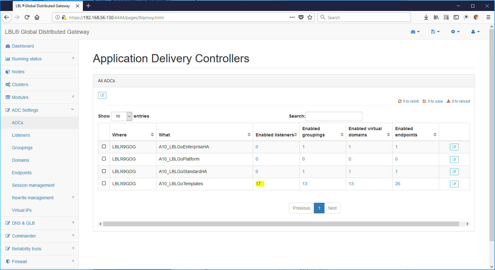
After login go to: ADC Settings > ADCs > Select templates listeners
With the list of template listeners go to search DNAT
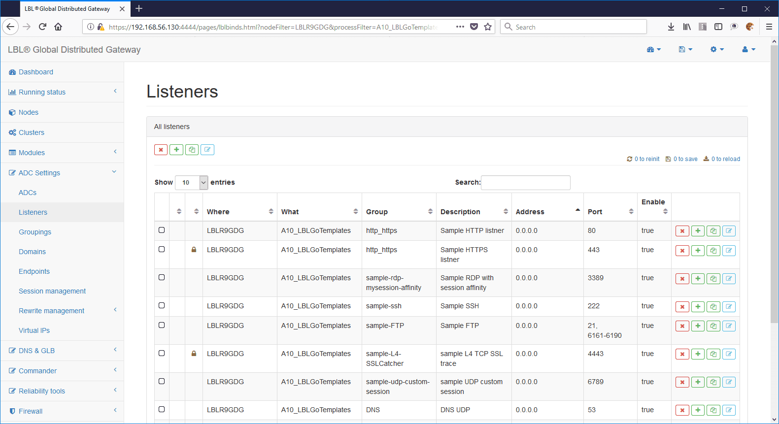
The search DNAT or DNAT_UDP highlights the Code Layer 2-3 binding template listener.
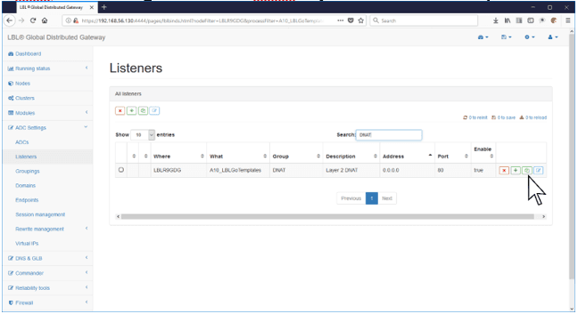
Copy the template listener to the module, in this case A10_LBLGoPlatform:
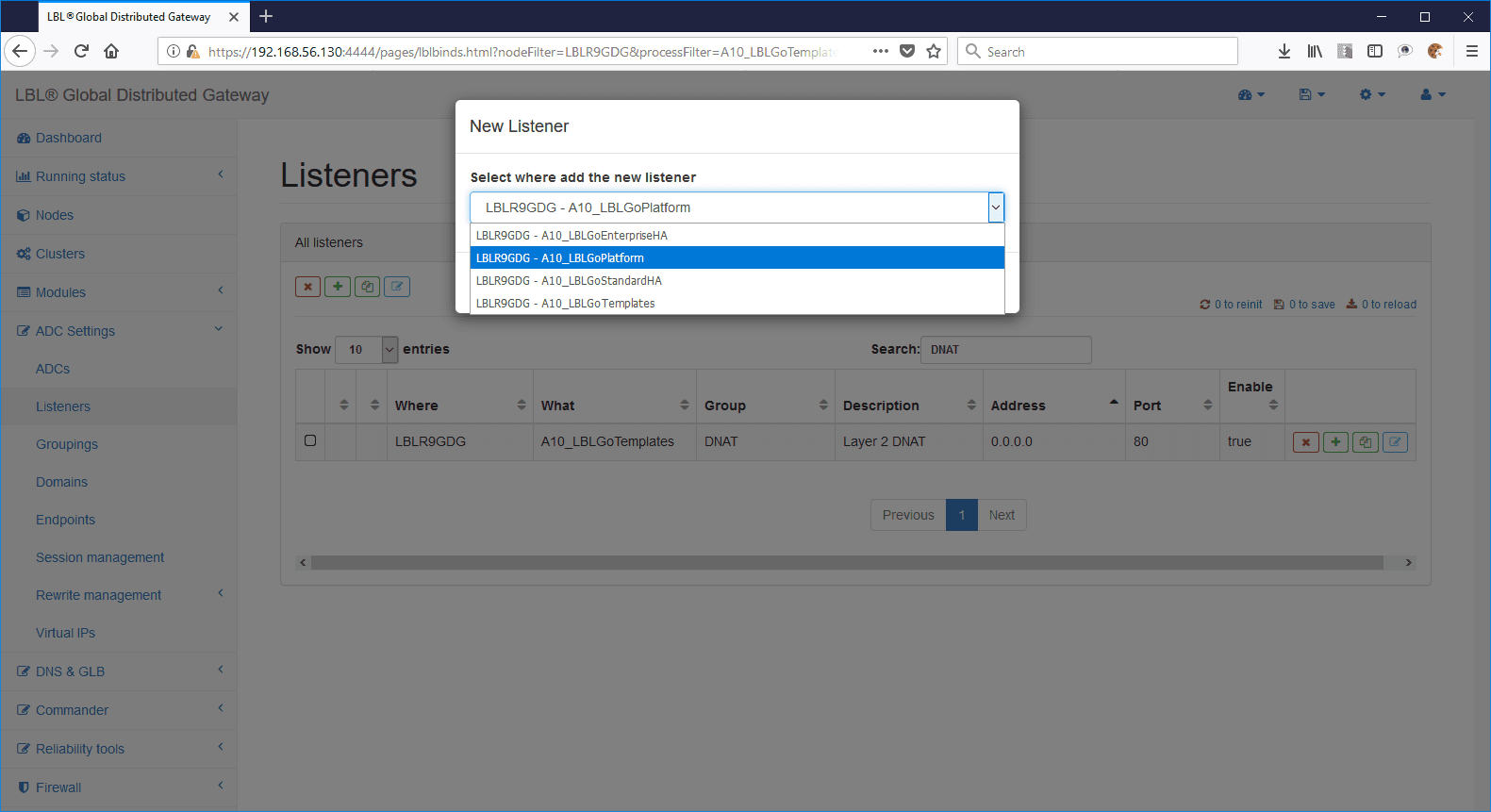
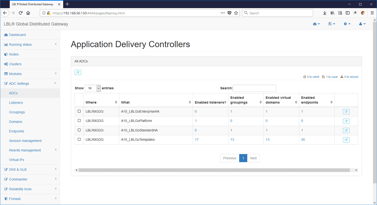
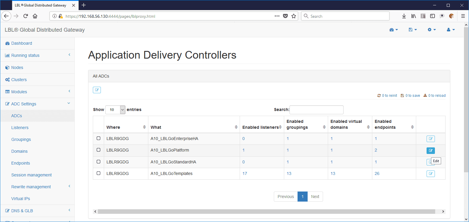
Returning to ADC Settings > ADCs the result is as follows:
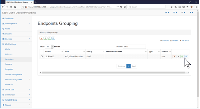
Repeat for the endpoint group as well:
On search type DNAT or DNAT_UDP:
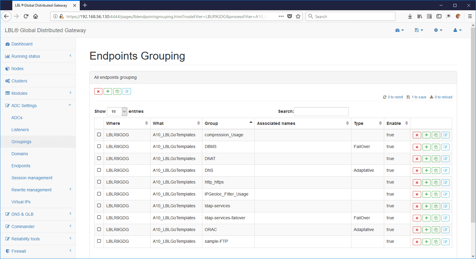
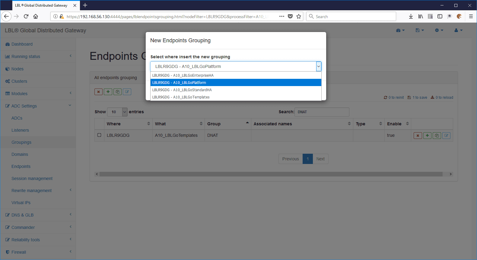
Once you type DNAT or DNAT_UDP copy the grouping template endpoint to the form, in this case A10_LBLGoPlatform:
Copying the grouping endpoint to the module:
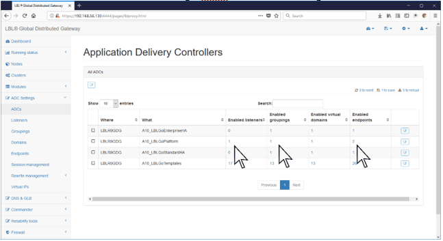
Returning to the ADC Settings > ADCs view the situation is as follows:
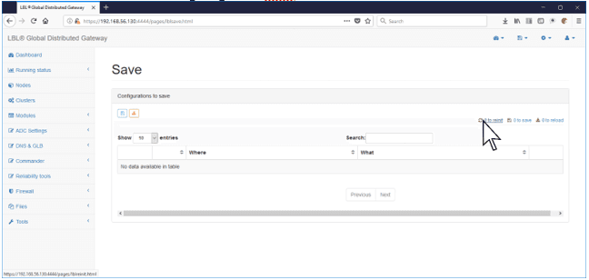
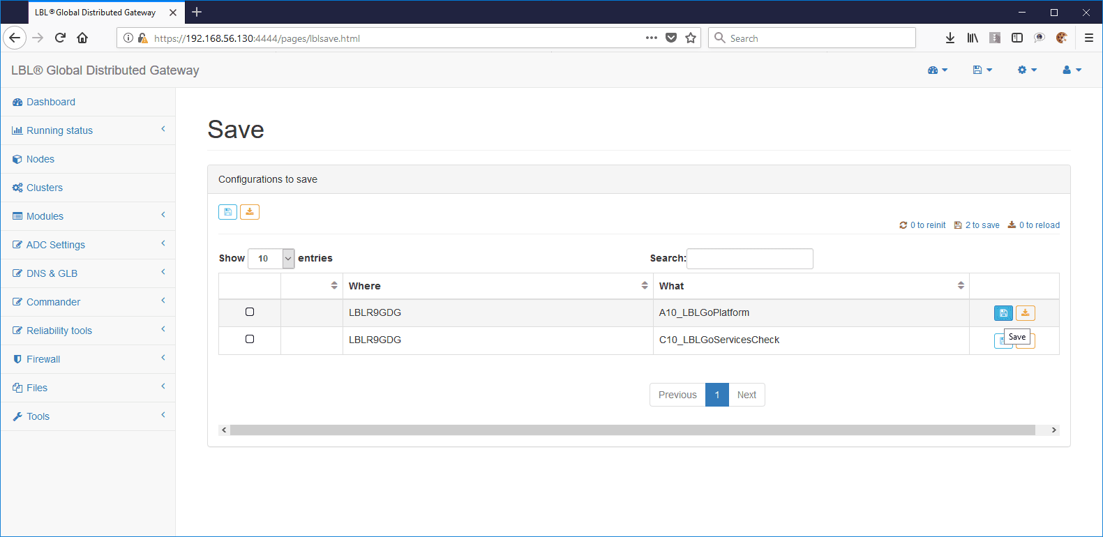
Save your settings so far:
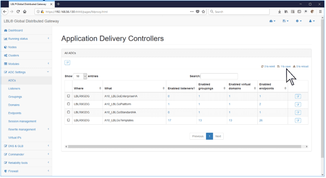
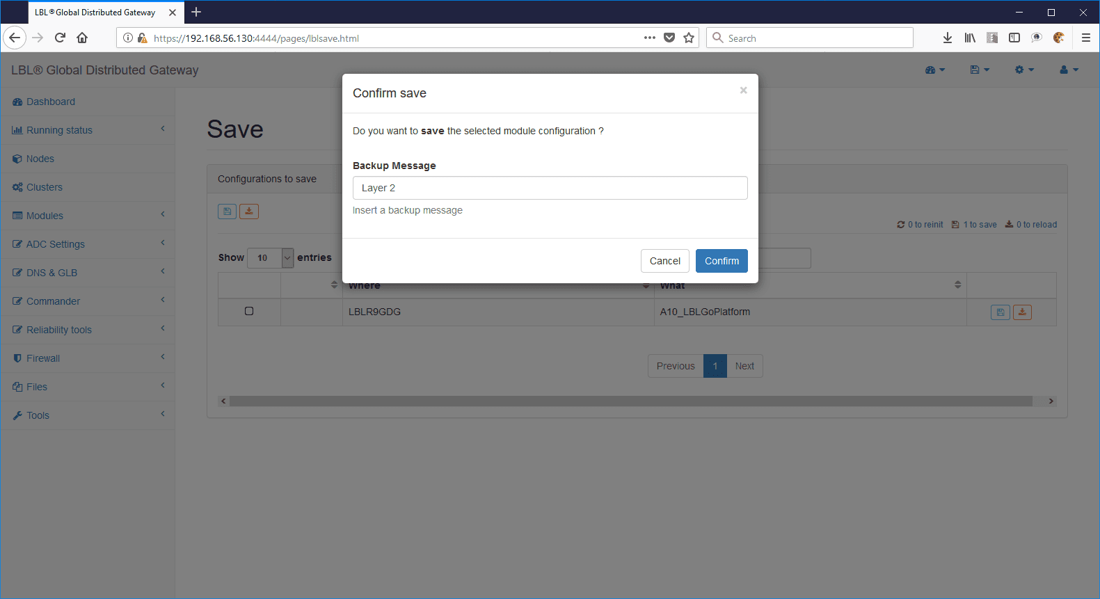
Save the proposed settings:
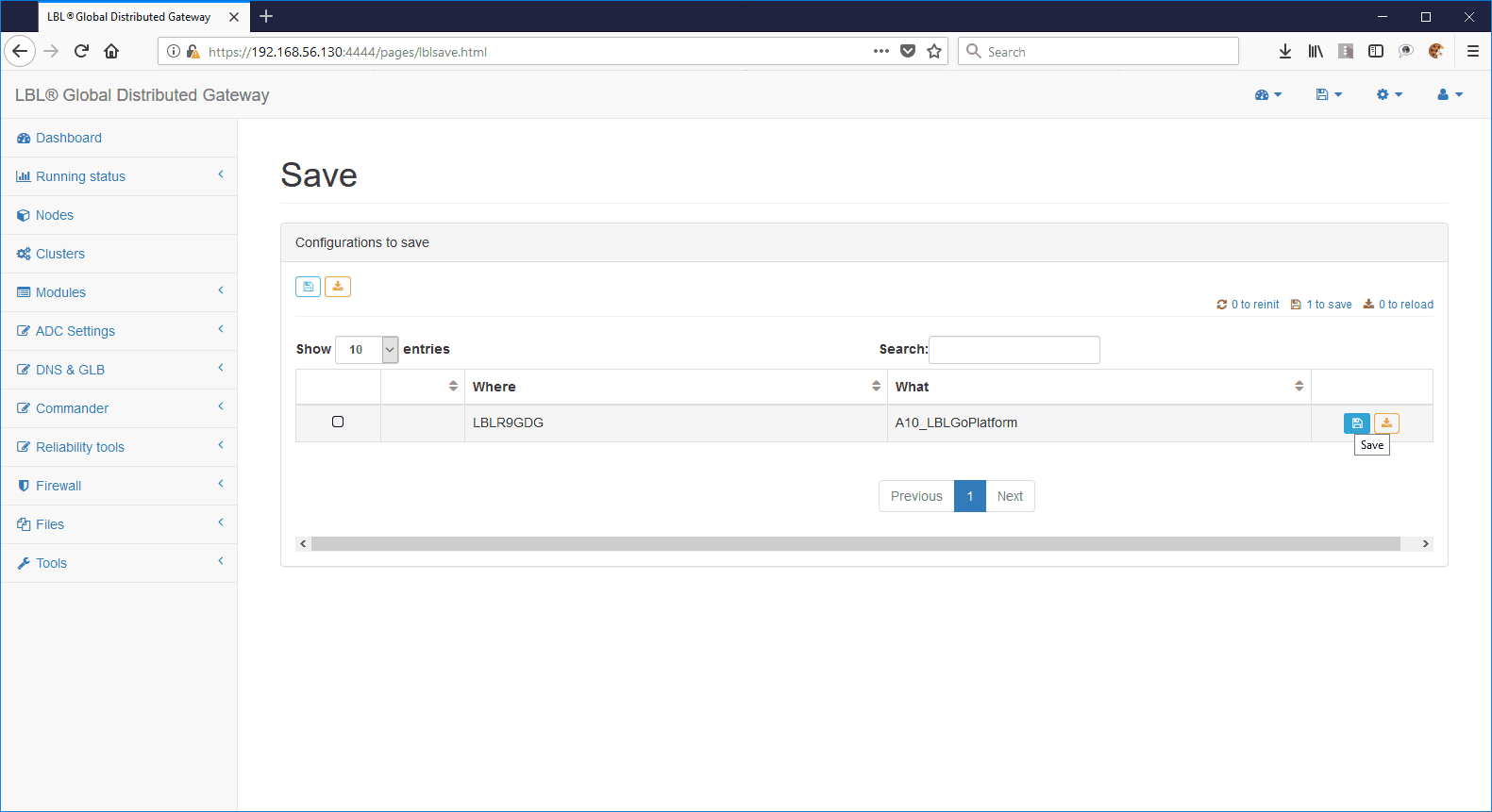
Indicate the reason for the save:
After you copy the Layer 2-3 templates to the module, associate the queues with the listener:
ADC Settings > ADCs > Edit module:
Expand the Listeners panel and press the See details button:
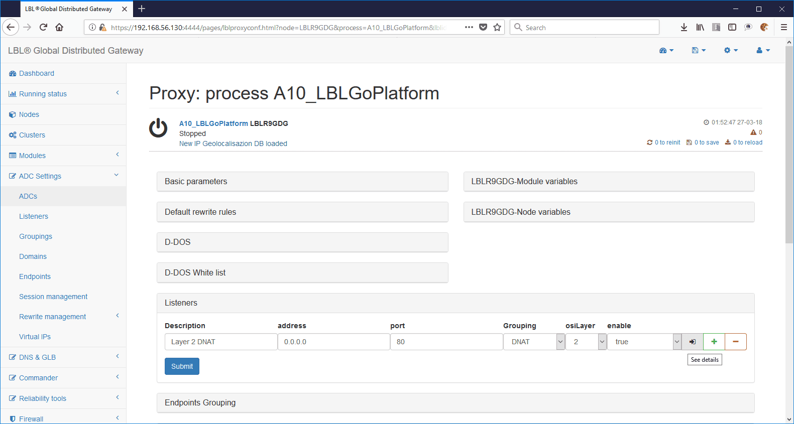
The listener will present the following carattristics: osiLayer set to 2; layer2QueueIn set to 0 and layerQueueOut set to 1. In this case you will not need to change the queues as we have previously generated them at 0 and 1 respectively.
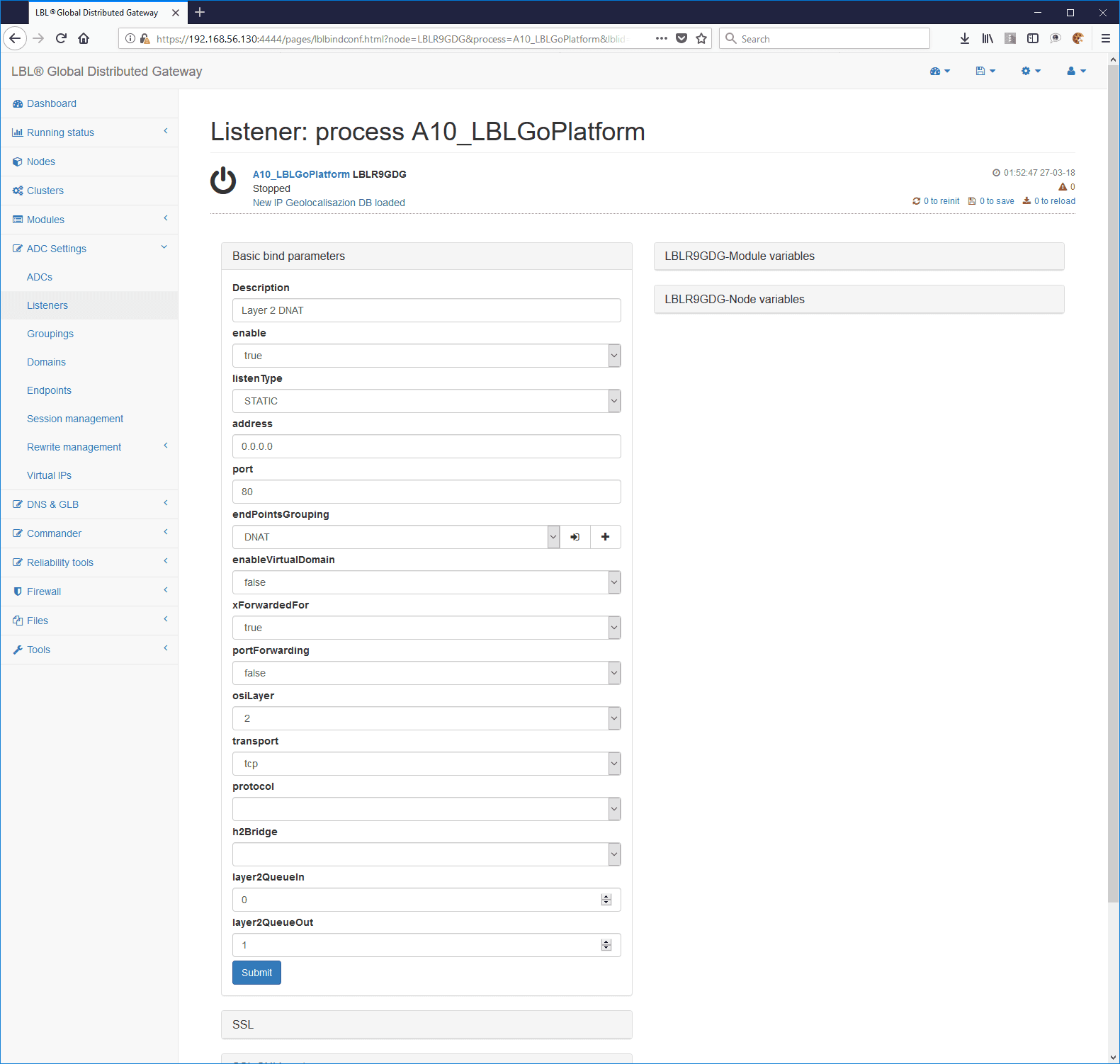
Also note that the listener address indication is 0.0.0.0 and the port is 80. These values are not taken into account because they are the queues that create the queue in a given NIC with certain filters. OPLON ADC will, however, transparently perform any port rewriting in case the packets have different ports between the packets received and the packets forwarded to the services.
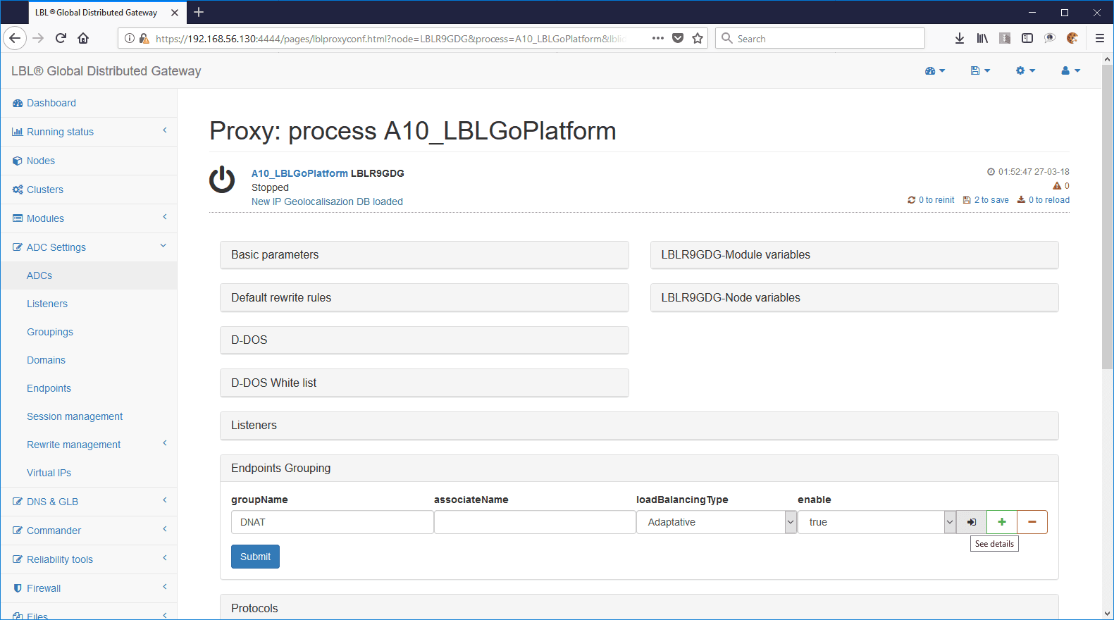
The treatment of routing to endpoints is perfectly similar to the treatment of layer 4. The addresses and ports to which the services respond will be indicated:
IMPORTANT: If the endpoint port is less than or equal to 0, the forwarding engine executes the port forwardig and reports the same input port to the packet. You do not need to set port forwarding on the listener, it will run automatically.
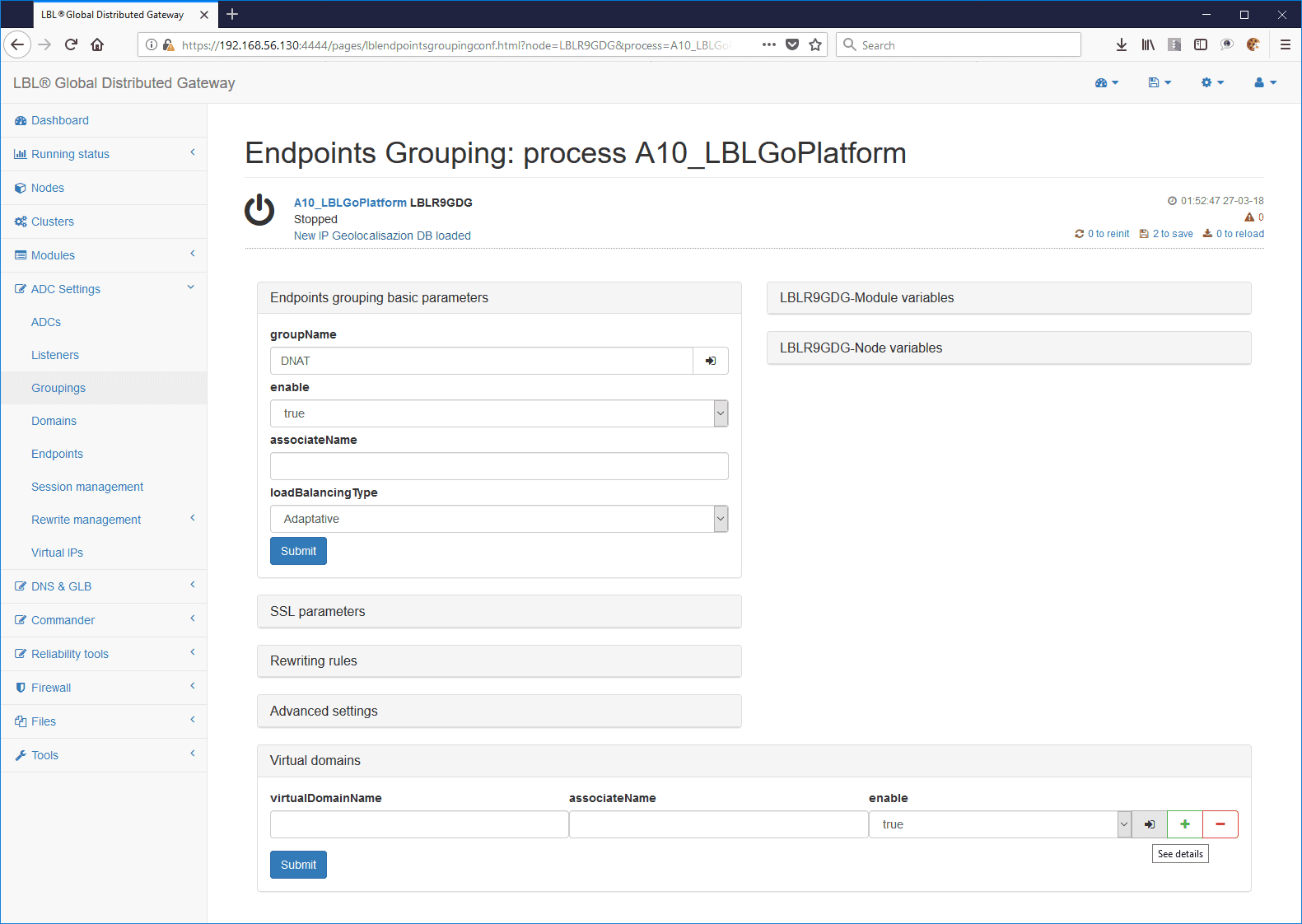
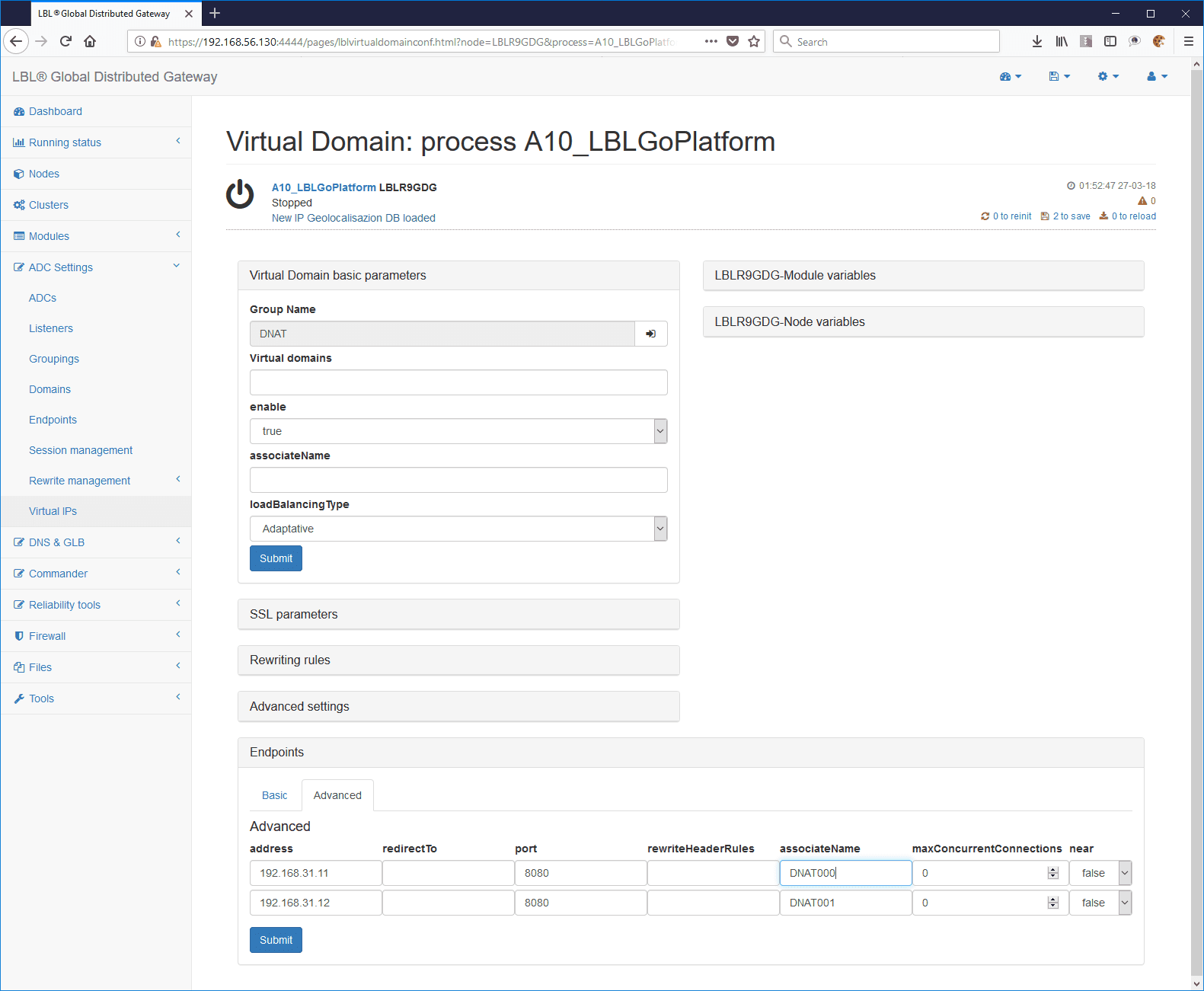
ADC Settings > ADCs > Edit on the affected form > Expansion of the Endpoints Grouping panel
Go into the domain detail (which in this case is empty):
Edit, add, or remove endpoits. In this case we have two endpoints that respond to port 8080.
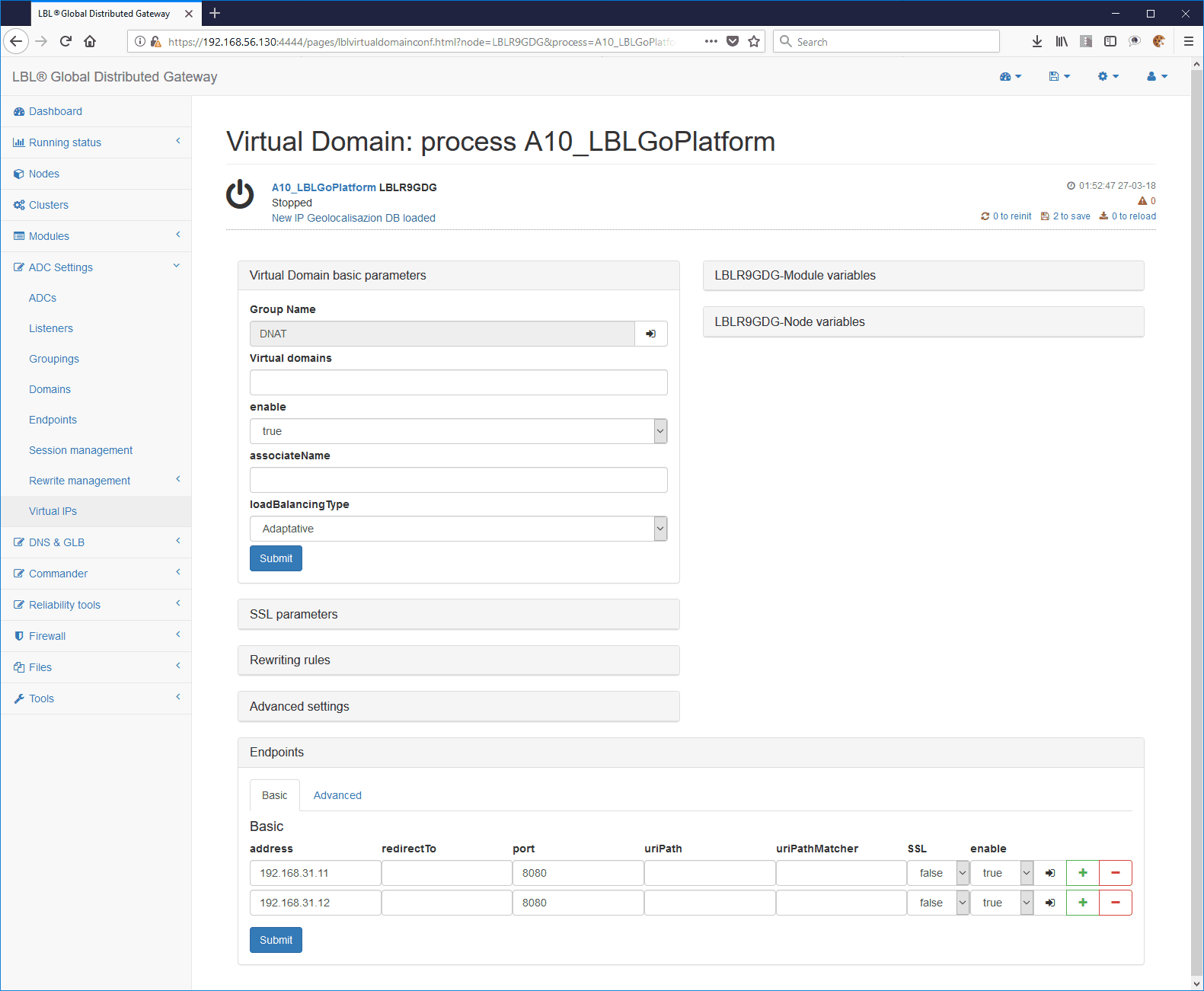
It is very important to assign associative names to endpoits because we will need them to perform healthchecks and disable routing in case of unattainability of one or more services.
If the module is running, re-run.
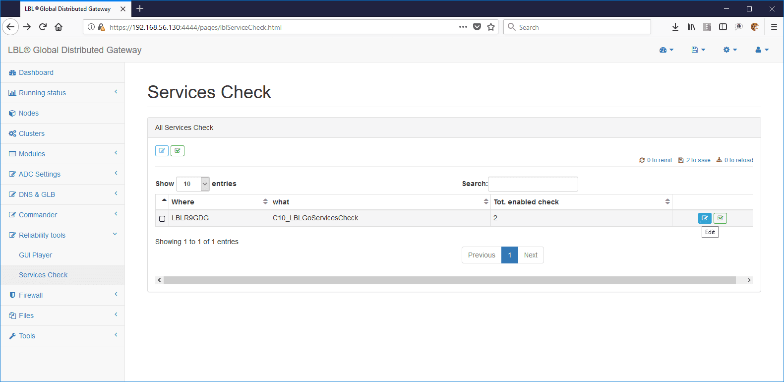
Service health check setting
The layer 2-3 system is able to redirect requests to surviving services based on their vitality. To be able to check the viability of the services set the healthchecks through the module: Reliability tools > Services Check > Edit
After the form is selected, set up health checks on services by assigning associative names:
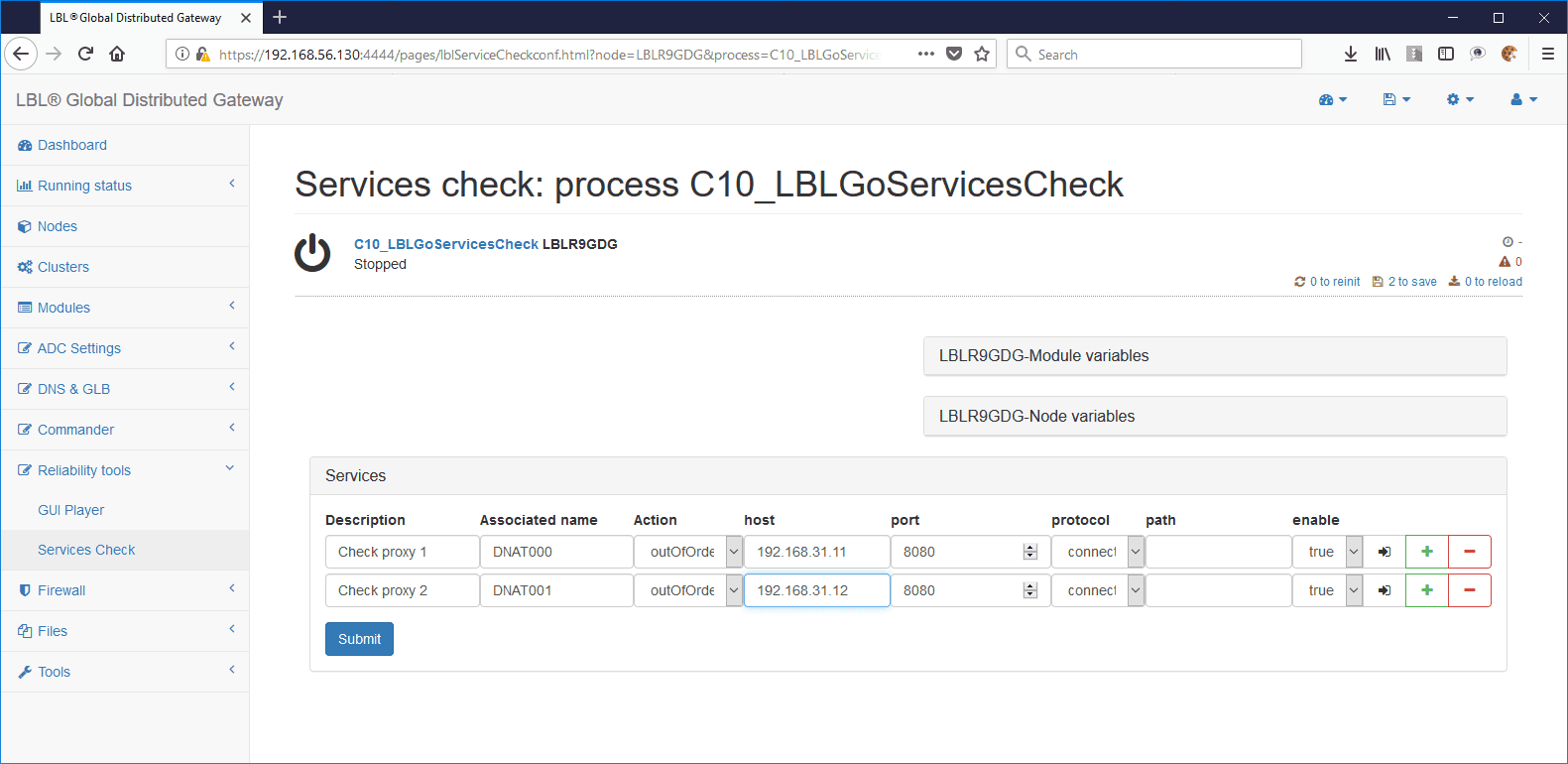
Save and run the following reinits:
Service-side routing setup (Linux)
For services to successfully route packets from the ADC, you must set up routing on the respective systems that contain the services.
Packages must be forced back into the source NIC with the tools made available to individual manufacturers of the operating system or products. The following is a non-exhaustive example of the topic but useful for interpreting and adapting it in individual installations:
Setting two mnemonic tables “1 rt_dnatnet” and “2 rt_internet”:
vi /etc/iproute2/rt_tables
#
# reserved values
#
255 local
254 main
253 default
0   unspec
#
# local
#
#1  inr.ruhep
1   rt_dnatnet
2   rt_internet
Set the root user to route packets from the ADC and how to set the gateway to ADC itself:
# ip route add 192.168.31.0/24 dev enp0s17 src 192.168.31.11 table rt_dnatnet
# ip route add default via 192.168.31.1 dev enp0s17 tab rt_dnatnet
# ip rule add tab rt_dnatnet from 192.168.31.11
To check low-level traffic and packet directions, run the following command:
# tcpdump -i enp0s17 port 80 or port 8080 or port 3128
Supports and templates
As a template, you can find a series of Linux routing-setting scripts at both the ADC and service level in:
(LBL_HOME)/legacyBin/Linux/ProxyDNAT
+---CentOSNetConfProxy
|   +---System000
|   |       CentOS_Simmetric.sh
|   |       CentOS_SimmetricInternet.sh
|   |       CentOS_SimmetricView.sh
|   |       ifcfg-BACKEND
|   |       ifcfg-DNATNET
|   |       ifcfg-INTERNET_DHCP
|   |       ifcfg-WIRELESS
|   |       README.txt
|   |
|   \---System001
|           CentOS_Simmetric.sh
|           CentOS_SimmetricInternet.sh
|           CentOS_SimmetricView.sh
|           ifcfg-BACKEND
|           ifcfg-DNATNET
|           ifcfg-INTERNET_DHCP
|           ifcfg-WIRELESS
|           README.txt
|
\---NetConfVAPP
        CentOS_NFQUEUE.sh
        CentOS_NFQUEUEView0.sh
        CentOS_NFQUEUEView1.sh
        CentOS_NFQUEUEView2.sh
        CentOS_NFQUEUEView3.sh
Persist routing rules
Attention: Routing rules and queue setup must be persisted and individual operating systems that provide services must be automatically set up and verified when individual VAPPs are restarted or operating systems that provide the services are automatically set up and verified